PlantUML Generator
Introduction and Motivation
The PlantUML tool lets you create UML diagrams quickly. You can generate UML component diagrams representing entire Context Maps, UML class diagrams for each Bounded Context in your model, and UML state diagrams to visualize an Aggregates lifecycle. If the implemented Subdomains contain Entities, the generator produces class diagrams for these Subdomains as well. We offer a transformation from our DSL into a graphical representation of the system this way. The component diagram illustrates all Bounded Contexts and their relationships, while the class diagrams show the domain models of the Bounded Contexts and Subdomains (if you used the Tactic DDD Syntax to specify them). In addition to that, it generates state diagrams to visualize your Aggregate’s lifecycles (in case you modelled the state transitions).
UML Component Diagram
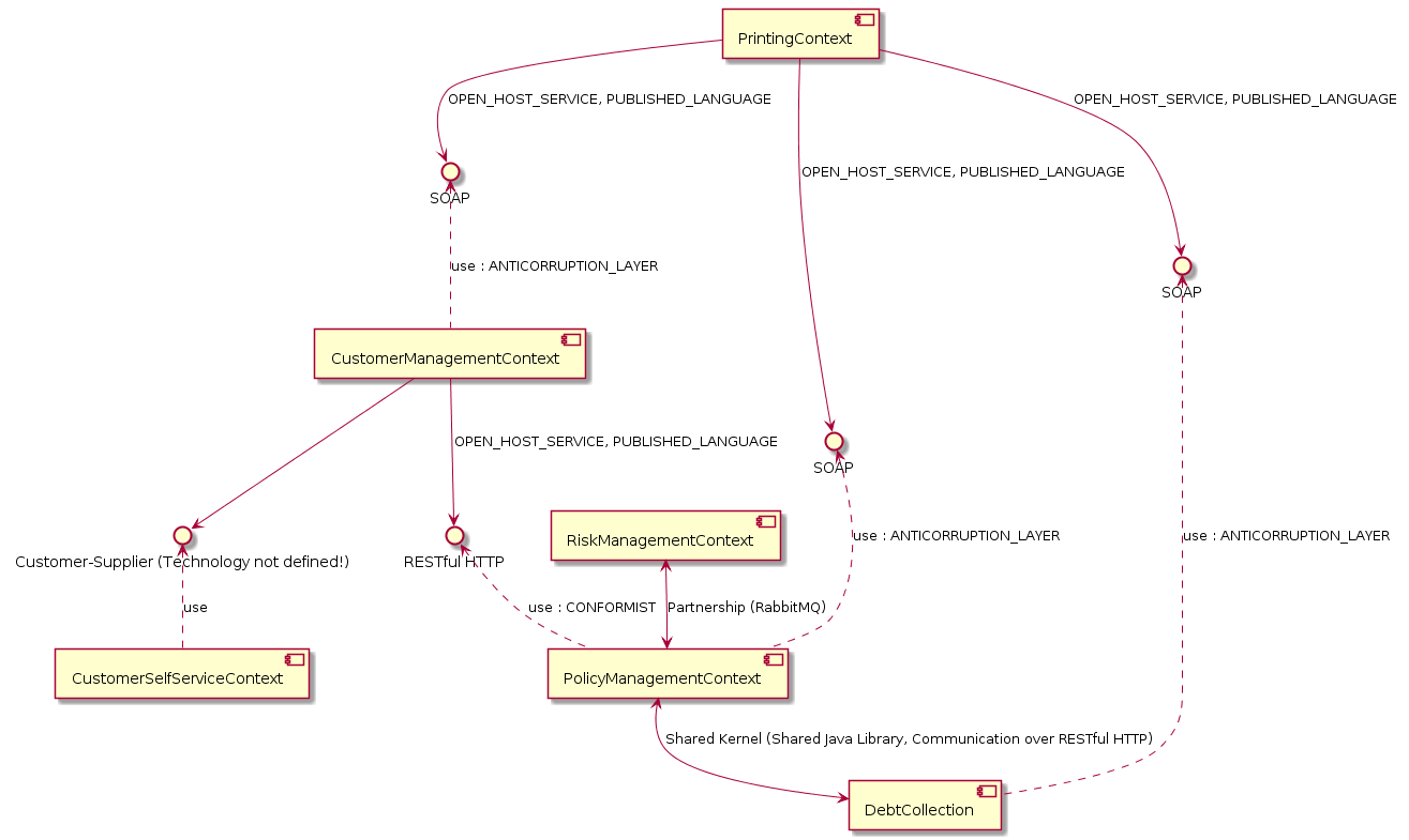
The generator creates a component diagram for your Context Map, showing the Bounded Contexts and its relationships. For example, the component diagram for our insurance scenario (example model) looks like this:
UML Class Diagram
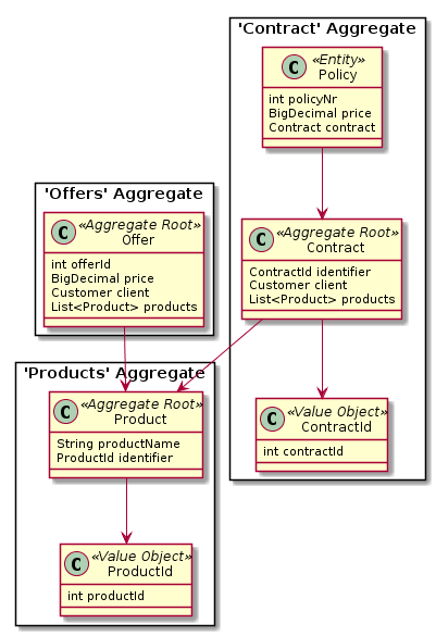
The generator also creates class diagrams for every bounded context and subdomain. An example from the insurance scenario is:
UML State Diagram
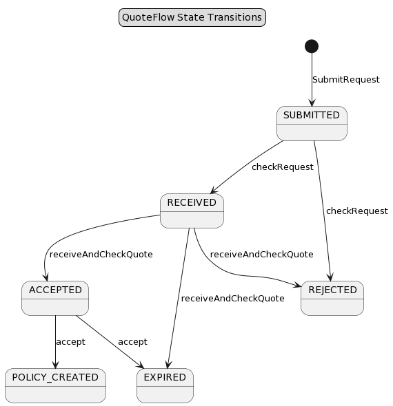
Your CML models can define the lifecycle of Aggregates either in the Aggregate itself or inside application flow definitions. If your model contains such state transitions, the generator will also create state diagrams for your aggregates or flows. An example from one of our models (Lakeside Mutual)
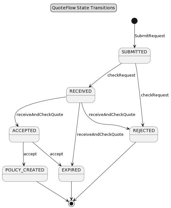
Note: If you you use the end state markers (*) as documented here, we also generate the corresponding end state transitions in PlantUML:
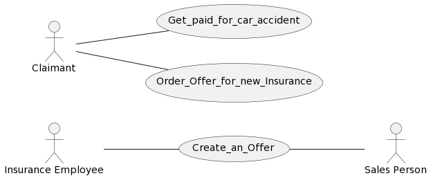
UML Use Case Diagrams
CML also allows you to write Use Cases and User Stories. You can find the documentation about how to write such user requirements here. In case your CML model contains such user requirements, the PlantUML generator will also automatically generate a use case diagram for you. Here an example:
Generating the PlantUML Diagrams
The generators can be called from the context menus of the CML editors in VS Code or Eclipse. A documentation how to call the generators can also be found here.
Once you generated the .puml files, you can of course not only view them in Eclipse or VS Code but also process them further. For instance, they can be integrated into Markdown and pandoc nicely.
Note: All generator outputs will be generated into the src-gen folder.